Turn and Bank Indicator
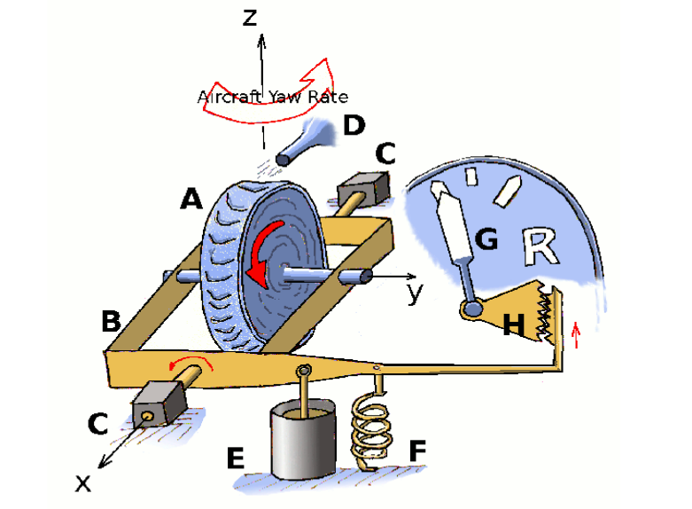
The gyroscope (A) is maintained at a high rotation rate using a jet of compressed air (D) produced by the engine manifold system. The gyroscope is supported on a frame (B) supported on gymbals (C) so that it is free to rotate.
If the aircraft is turning (about axis z) the yaw rate coupled with the gryo spin rate (about axis y) will produce a cross product vector or angular acceleration and hence a rotation about orthoginal axis (x). Effectively the gyro is trying to precess due to the applied aircraft rotation. Free rotation about axis x is moderated by the spring (F). The force in this spring conteracts the tendency for the frame to rotate due to the precession and will be proportional to the turn rate.
A damper (E) is used to remove unwanted vibration. The gearing (H) translates the restricted motion of the frame to an indicator (G) showing the turn rate.