FLOW VISUALISATION
Of extreme importance before attempting to analyse an aerodynamic flow is to understand the behaviour of the flow. This can be done by making the flow visible. The introduction of smoke lines to follow the airflow, the addition of surface tufts, oils or sensitive pigments are all methods to allow the investigator to "see" what is happening. These visualisations can then be used to infer the nature of the flow in terms of circulation, vortex effects, flow separations and turbulence. This allows appropriate choices or simplifications of the equations used to solve the flow. Without such visualisation, incorrect assumptions will lead to the solution of flow cases that may not be directly relevant to the problem being considered and hence may lead to large errors. Some examples of flow visualisation are shown below.
Some examples of flow visualisation are shown below. Click on the flow images to view animations of the flows.
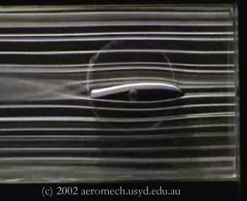 |
Aerofoil section flow Smoke visualistion of flow around two dimensional aerofoil section. Note:
|
 |
Vortex Wing Tip Flow. Smoke visualistion of flow around three dimensional wing showing tip formation of trailing vortex flow. Note:
|
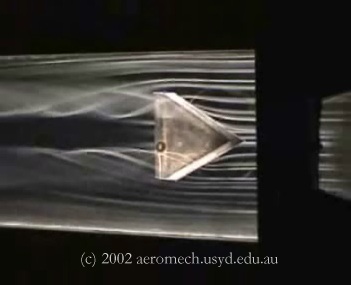 |
Delta Wing Vortex Pair. Smoke visualistion of flow around three dimensional delta wing showing surface vorticies formed from leading edge separation. Note:
|
 |
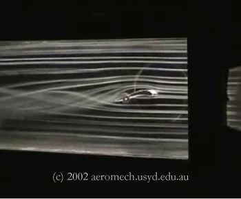
Aerodynamically Designed Car. Smoke visualistion of flow around three dimensional sports car showing centerline flow. Note:
|
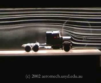 |
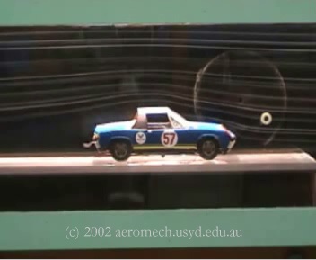
Square Edged Truck. Smoke visualistion of flow around three dimensional truck showing centerline flow. Note:
|
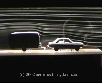 |
Car, Caravan Combination. Smoke visualistion of flow around three dimensional car and caravan model showing centerline flow. Note:
|
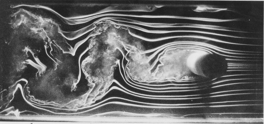 |
Low Reynolds number Cylinder. Smoke visualistion of flow in wake of Circular Cylinder. The flow is pre-critical with separate at extreme radius. This forms a set of alternating shed vortices in the wake. |