Altimeter
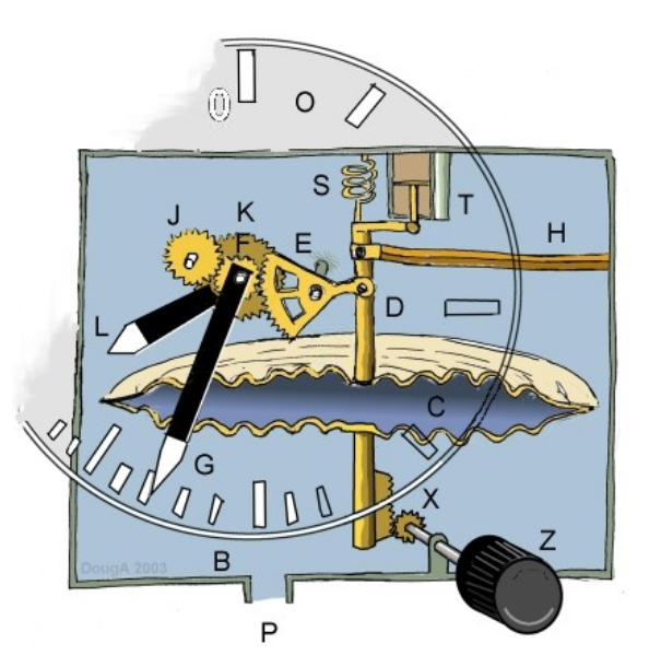
A schematic representation of a typical altimeter is shown with components indicating the method of operation. Pressure from the static port (P) enters the instrument (B) and surrounds the cannister (C). The cannister is sealed and so will have a constant internal pressure.
As the altitude of the aircraft increases the cannister will be surrounded by a reduced static pressure. The pressure difference will expand the cannister (C) moving rod (D) hence rotating gears (E) and (F) to give an angular movement of the indicator needle (G).
Needle (G) will typically indicate pressure altitude in 100’s of feet and will complete one revolution of the dial every 1000 feet. Secondary gears (J) and (K) will scale the rotation for indicator (L) so that it will typically indicate pressure altitude in 1000’s feet on scale (O). This means that the altimeter has a reasonable range of measurement as well as the required sensitivity.
The altimeter is calibrated by adjustment of spring (S) at manufacture. The instrument will need to be “zeroed” to the correct pressure altitude for the locality as meteorological conditions will change the local sea level pressure. This offset is achieved by turning the zero knob (Z) which will set an initial displacement position for rod (D) giving the required initial pressure altitude at ground level.
Vibration damping is provided by dashpot (T) and movement in cannister or rod components due to thermal changes is compensated for by a bi-metal system (H).