Vertical Speed (Climb/Descent)
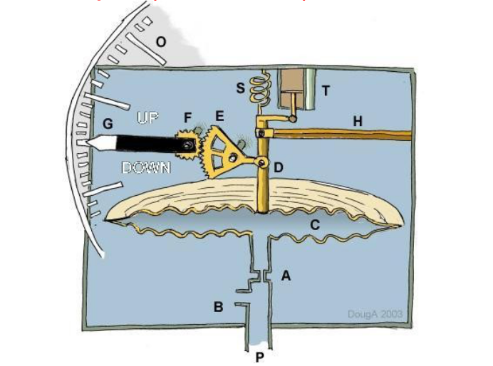
A schematic diagram of a vertical speed indicator is shown, with the typical components and an indication if their mode of operation.
Pressure from the static port (P) enters the instrument via tube (B) and surrounds the cannister (C). Pressure from the static port (P) also enters the cannister (C) via a fine metered tube (A).
When the aircraft is flying at a constant altitude, the pressure inside the cannister will be equal to the surrounding pressure, so that a zero reading will result. If the aircraft is climbing, the pressure inside the cannister will lag behind the static pressure due to the restricted flow rate at (A). Based on the calibrated size of tube (A), the pressure difference between inside and outside the cannister is proportional to the rate of change of altitude. The pressure difference will expand the cannister (C) moving rod (D) hence rotating gears (E) and (F) to give an angular movement of indicator needle. (G).
A scale (O) shows typically ft/min (feet per minute) climb rate and is calibrated by adjustment of spring (S) at manufacture.
If the aircraft is descending, there will also be a lag between internal cannister pressure and surrounding static pressure. In this case the internal pressure will be lower, the cannister will contract and a negative reading (or descent rate) will be shown.
Vibration damping is provided by dashpot (T) and movement in cannister or rod components due to thermal changes is compensated for by a bi-metal system (H).