AIRCRAFT PERFORMANCERotary Wing Aircraft |
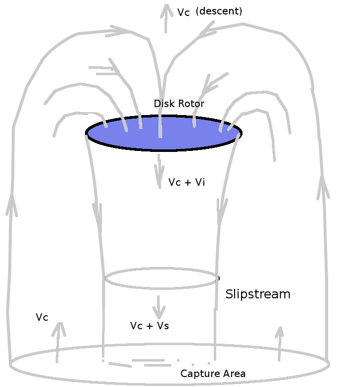
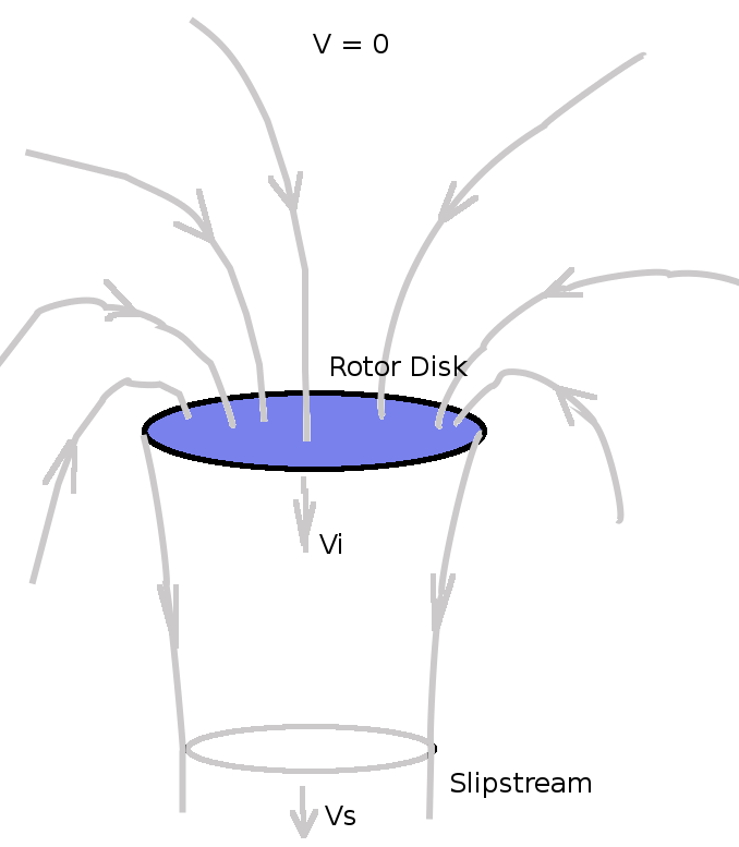
MOMEMTUM DISK ANALYSISThe helicopter rotor can be idealised as a “momentum disk”. It imparts a uniform velocity (vi) to the airflow creating a change in momentum which will result in an upward thrust (T). HOVERFor the hover case air is sucked in from all directions so the farfield inlet velocity is effectively zero, accelerated to vi at the disk and then propelled to a final slipstream velocity of vs below.
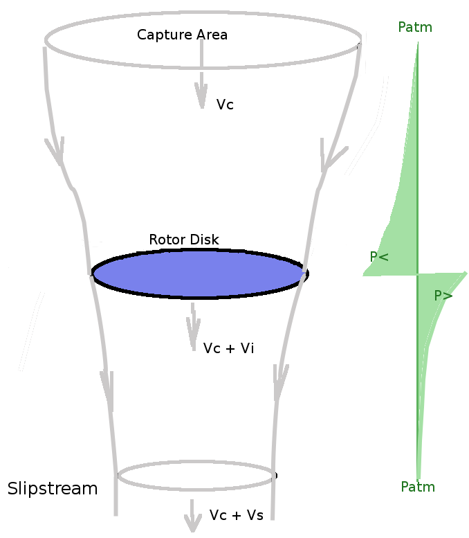
If the area of the disk is A then the mass flow of air, m, being accelerated is The change in momentum of the stream will be $ ΔM = m v_s $ and this will be equal to the force produced, the thrust. The change in Energy per unit time of the stream will be The work done per unit time on the air by the rotor thrust is $$ 1/2 ρ A v_i v_s^2 = T v_i = ρ A v_i^2 v_s $$ giving Hence thrust of the ideal rotor in hover is As the rotor thrust is required to be equal to the weight of the vehicle, it is possible to use this equation to predict the induced flow required to maintain hover, CLIMBFor the case where the helicopter is climbing, the rotor will capture flow from a fixed area above and accelerate this to a final slipstream velocity. The momentum balance will be slightly different as the incoming air has an initial momentum due to the helicopter climb speed and the rotor is just augmenting this. The mass flow rate through the disk will be, The thrust due to momentum change will be
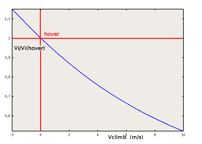
Applying and Energy balance will again lead to $ v_s = 2 v_i $ so that Rearranging gives Solving this quadratic equation for vi gives or The required variation in induced velocity for climb is shown in the following figure
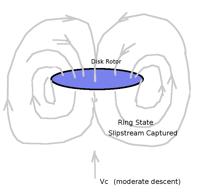
Less induced velocity is required for climb as the momentum change applied to a higher initial velocity is more effective. DESCENTDescent can be analysed by using a negative value of $V_c$ in the above equations. However there are physical limits on this approach due to the changing flow pattern. As the capture area is now below, problems will arise as the rotor is now capturing its own wake an recirculating it to create momentum change. Eventually at a higher rate of descent the system will become closed and the rotor will simply recycle its own wake ('ring state'). In this condition there is no momentum change and hence no thrust.
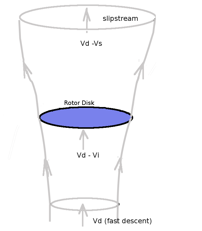
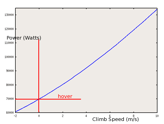
If the above stable ring flow state can be avoided, a fast descent can be achieved which puts the rotor in to a windmill state. Capture area is still below but rotor is absorbing momentum from the stream and a divergent slip stream appears above. This negative change in momentum will again produce a thrust (a vertical drag). This flow state can be used for autorotation of the blades. POWER REQUIREDEngine power is required to be supplied to the disk in order to produce the required thrust. There will be two components of power requirement in this simple analysis. Power is required to produce the momentum change ( $ P_1 = T v_i $ ) and power is required to make the helicopter climb ( $ P_2 = T V_c $ ). Neglecting power losses in transmission, fuselage drag components, blade profile drag power, etc. The the power required for the operation of the ideal rotor will be Again assuming climb rates are small so thrust approximately equals weight , the variation of power required for different climb rates is shown in the following figure.
|
 The
variation of pressure will drop below atmospheric above the disk,
increas due to the energy input of the disk and then drop bad to
atmospheric in the slipstream.
The
variation of pressure will drop below atmospheric above the disk,
increas due to the energy input of the disk and then drop bad to
atmospheric in the slipstream.